Article 434.5.2 of standard NF C 15-100 :
The breaking time of any current resulting from a short-circuit at any point in the circuit must not exceed the time required to bring the conductor temperature up to the permissible limit.
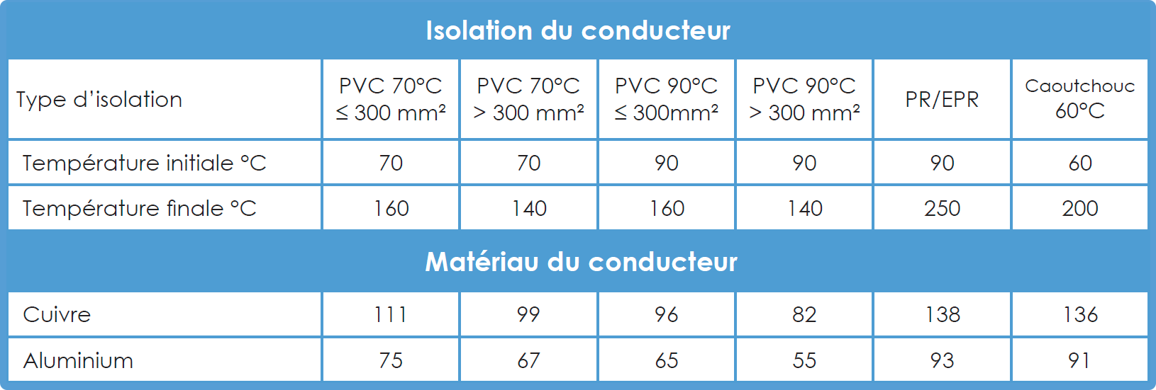
For short-circuits lasting up to 5 s, the time required for a short-circuit current to raise the conductor temperature from the maximum permissible temperature in normal operation to the limit value can be calculated as a first approximation using the following formula :

Where:

In elec calc™ :
The permissible thermal stress of a cable is its capacity to withstand a circuit current during its elimination time without the insulation being damaged.
The value of the thermal stress is expressed in A².s (I²t).
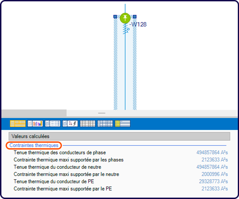
In the absence of a manufacturer’s reference upstream of the conductor, the thermal stress on the conductor is calculated as a function of the maximum short-circuit current seen by the cable and the circuit-breaker opening time: I² x t (I in A and t in s).
This value must be less than the thermal resistance of the cable: k²xS².
Where:
What’s the solution? Integrate a manufacturer reference on the upstream circuit breaker:
To avoid oversizing the cable cross-section, manufacturers incorporate a limiting effect in most protections.
Limitation is read directly from a manufacturer’s curve for upstream protection (circuit-breaker or fuse): the energy limitation curve. It defines the maximum thermal stress borne by the conductor, according to the maximum short-circuit current flowing through the pipe.
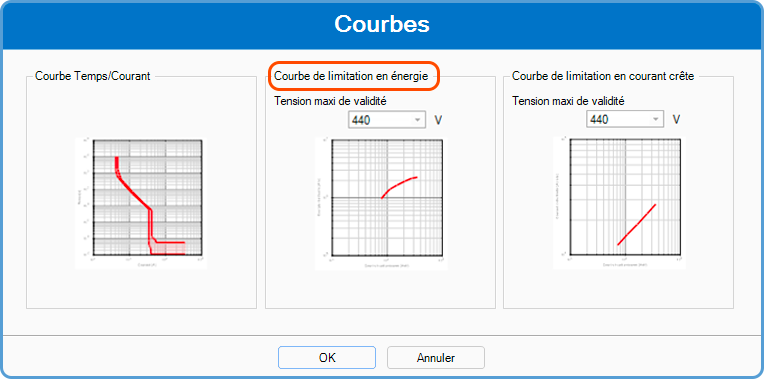
Interpretation of thermal stress values in elec calc™ :

If i²t > k²s², a thermal stress anomaly appears on the cable.
For more information, see this article on checking thermal stresses in a conductor.
You can also find the tutorial on thermal constraints below:


