Through-energy and permissible thermal stress
Among the intrinsic characteristics of a cable or conductor, two values are essential for its dimensioning:
For standardized cables, these values are imposed by the standard, e.g. 90°C and 250°C respectively for PR/EPR insulated cables.
It is therefore important to check that the passage of the short-circuit current (Ik) during the fault clearance time (t) will not cause the cable core to exceed its maximum temperature.
For a fault clearance time of less than five seconds (hence the maximum imposed by installation standards), heating is considered adiabatic, i.e. the heat generated remains at the core level and has no time to dissipate to other parts of the cable.
In this case, the thermal stress borne by the conductors is calculated by the formula :
Through energy = Ik² x t in A²s.
The permissible thermal stress of the conductor is calculated by the formula k2 x S2, where
It is therefore necessary to check that, in all short-circuit cases, the relationship is verified:
Ik² x t < k² x S²
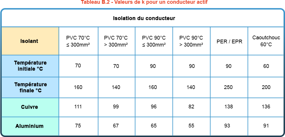
To make calculations easier, you can use the tables giving k values for common cases, as in the following example from FD C 15-500:

The elec calc™ software calculates the maximum through energy on all conductors and compares it with their thermal resistance (according to the formula k²xS²). This check applies not only to phases, but also to neutral and PE. If this condition is not met, a thermal stress error is displayed on the cable.
How to solve a thermal stress problem
In the event of thermal stress problems, it is always possible to oversize the conductor cross-section, thus increasing the permissible thermal stress. However, there are other ways of eliminating the need to increase conductor cross-section.
Use of fuses: the melting time of a fuse is generally much shorter than the opening time of a circuit-breaker for high short-circuit currents. There is therefore a natural limitation of the energy passing through. Note that with fuse protection, maximum energy may occur during the minimum short-circuit, as the melting time may be longer. It is therefore necessary to check the cable’s resistance to all types of short-circuit current.
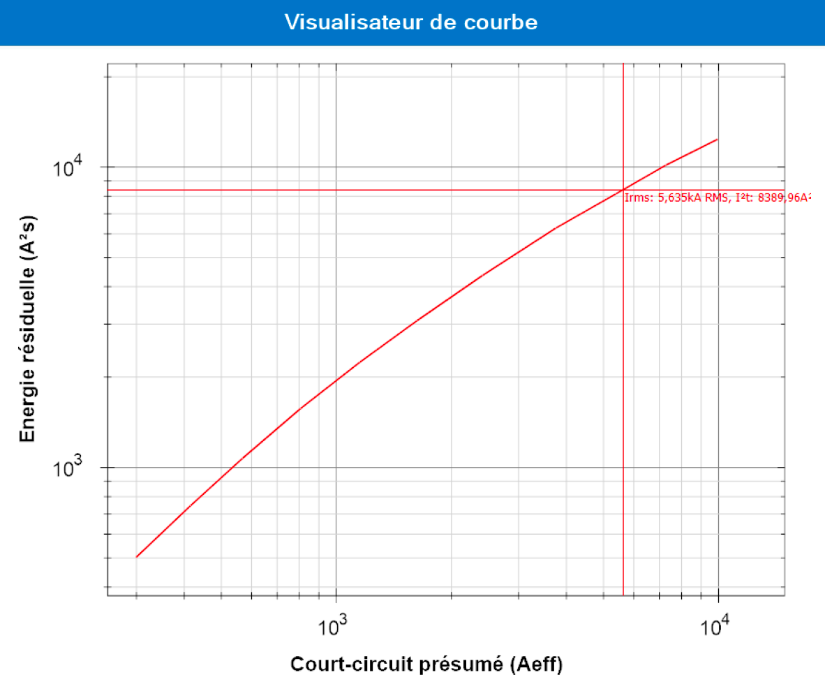
Use of limiting circuit-breakers: certain ranges of equipment are designed to prevent fault currents from building up, by allowing only a limited current to flow. The limiting performance of a circuit-breaker is given by the manufacturer in the form of limiting curves:
Theelec calc™ multi-manufacturer catalog manages the limitation curves of the various protections. As soon as a hardware reference with a limitation is associated with a protection, the software will be able to retrieve the limited energy associated with the presumed short-circuit current.
It should be noted that most modular circuit-breakers have limiting capabilities, enabling them to solve thermal stress problems in small-section pipes, which are most affected by thermal stress problems.
Example:
My installation includes a lighting circuit with a U1000R2V-3G2.5 cable protected by a 16 A curve C circuit breaker. The maximum short-circuit current on the cable is 5.63 kA and the protection trip time is 10 ms.
The maximum energy is therefore : Ik² x t = 5.63²x0.01, i.e. 316,969 A²s
The thermal resistance of my cable is: k² x S² = 138²x2.5², i.e. 119,025 A²s
Check: Ik² x t > k² x S² => problem of thermal stress on the cable: in the event of a short-circuit, the cable will be damaged.
Fuse :
If I replace the circuit breaker with a 16 A gG fuse, the melting time is 4.10-5s.
The maximum energy is therefore : Ik² x t = 5.63²x0.00004, i.e. 1268 A²s
There is therefore no problem of thermal stress on the cable.
In our case, we have also verified that it is the maximum short-circuit current that gives the maximum energy.
Integration of a circuit-breaker reference with limitation :
I’m now integrating a hardware reference on my protection. The software will therefore be able to read the residual energy for a circuit current of 5.63kA from the energy limitation curve supplied by the manufacturer:
In our case, the residual energy is 8,389 A²s. This is less than the thermal resistance of the conductor. So there’s no longer any problem of thermal stress on the cable.

Accuracy of through-energy calculation
Taking the DC component into account: in the above formulas, we have assumed that the value of Ik is the RMS value of the AC component of the presumed fault current. If we want to be more precise, we need to take into account the DC component of the fault current. The influence of this DC component is particularly noticeable when the fault point is close to the sources. It depends on the fault clearance time and the value of the X/R ratio of the circuit at the fault point. In this case, we need to calculate an equivalent thermal current, which replaces the Ik current in the
formulas.
elec calc™ takes into account the influence of this DC component when the standard used requires it.
Multiple sources: a fault may be supplied by several sources, each contributing to the short-circuit current. The protections associated with these different sources may not react at the same time to the short-circuit current they generate. Precise calculation of the energy flowing through the fault must therefore take into account the chronological accumulation of the energies produced by each source.
This is what the elec calc™ software does, to get as close as possible to the real phenomenon.


